To test your headlight relay, start by swapping it with an identical relay from another vehicle system to confirm functionality. Listen for an audible click when activating the headlights, and visually inspect the relay for corrosion or damage. For precise testing, use a multimeter to measure coil resistance between terminals 85 and 86 (expect 50-120 ohms), then check continuity between terminals 30 and 87 while applying 12V to the coil. The following sections detail advanced diagnostic techniques and professional testing methods.
What Is a Headlight Relay and How Does It Work?
The relay functionality overview shows that most automotive relays use either 4-pin or 5-pin configurations. Terminals 85 and 86 connect to the control circuit, while terminals 30 and 87 handle the high-current load. This design reduces voltage drop, prevents switch damage, and guarantees reliable headlight operation throughout your vehicle’s electrical system.
Common Signs Your Headlight Relay Is Failing
Recognizing headlight relay failure symptoms allows you to diagnose electrical issues before they compromise vehicle safety. Headlight issues manifest in several distinct patterns: complete failure where lights won’t activate, indicating the relay’s stuck in the open position; intermittent operation with flickering or inconsistent function; or lights remaining on continuously due to contacts welded in the closed position, causing battery drain. You’ll notice specific beam failures—low or high beams independently malfunctioning based on which relay has failed. Electrical diagnosis includes identifying clicking or buzzing sounds near the relay location, signaling worn internal components struggling to complete circuits. Dimming or uneven brightness between headlights indicates unstable voltage distribution. Moisture and humidity can penetrate the relay housing, degrading internal conductivity and causing erratic headlight performance. In vehicles with concealed headlights, relay failure causes erratic door operation, further confirming electrical malfunction requiring immediate attention.
Quick Test: Swap the Relay With Another Compatible Relay
Swapping your headlight relay with an identical unit from another vehicle system provides the fastest diagnostic method when troubleshooting headlight failures. Begin with relay identification by consulting your owner’s manual to locate the fuse box and pinpoint the headlight relay. Perform a compatibility check by finding another relay in the same box with matching part numbers and pin configurations—common candidates include horn or AC compressor relays. Pull both relays firmly from their sockets, then install the compatible relay into the headlight socket. Turn on your headlights to test functionality. If they illuminate properly, you’ve confirmed the original relay is faulty. If problems persist, investigate wiring or bulb issues. Before removing the relay, inspect the connector pins for corrosion or dirt that could affect the connection. Always verify the vehicle is off during relay removal to prevent electrical hazards.

[OE] 15016745, 1R1944, RY560, 13506836.

Specification: This 9007 headlight relay harness with 2pcs 9007 plug headlamps,14AWG wire gauge,built-in two durable relays, high-temperature ceramic headlight sockets, can well proect the car circuit if there is any abnormal situation occur. Wiring harness only, not a Headlight

Versatile Compatibility: The G8HL-H71 relay 12 VDC is the perfect solution for powering various vehicle accessories, including A/C compressors, headlights, horns, fans, and more.
Listen and Look: Testing by Audible Click and Visual Inspection
One of the simplest diagnostic methods involves listening for the relay’s audible click while simultaneously performing a visual inspection of the component. Have a helper activate the headlights while you listen near the relay location. A working relay produces a soft click sound as the electromagnet engages the contacts. No click suggests power supply issues or internal failure. Rapid, repetitive clicking indicates deteriorating contacts. While listening, inspect the relay condition for corrosion, melted plastic, or burnt spots on the casing and terminals. Check that the relay sits firmly in its socket with clean, undamaged terminals. Feel the relay during activation to confirm physical contact movement. Always consult your vehicle’s safety manual before performing any electrical diagnostics to ensure proper precautions are followed. This combined approach quickly identifies obvious faults before proceeding to multimeter continuity testing for definitive diagnosis.
How to Test a Headlight Relay With a Multimeter
Testing a headlight relay with a multimeter requires identifying the relay’s terminal configuration before proceeding with electrical measurements. Begin with relay pinout identification by locating terminals 85 and 86 (coil) and 30, 87, and potentially 87a (switch contacts). Remove the relay from its socket and set your multimeter to resistance mode. First, measure coil resistance between terminals 85 and 86; expect 50-120 ohms for a functional coil. Next, perform a continuity check analysis on the switched contacts. Without voltage applied, terminals 30 and 87 should show infinite resistance (open circuit). Apply 12V to the coil terminals, then retest; you should measure near-zero ohms between 30 and 87, confirming proper switch closure and relay operation. Resistance readings outside the acceptable range may indicate a shorted coil or open coil that prevents the relay from functioning correctly.

EASY TO USE - The tester will automatically detect the pin position, the release time of the action, and the consistency of the relay in each test phase. If the tester lights up the green LED light, the relay is normal; if the red LED light is on, the relay is abnormal. The relay puller makes it easy to remove the relays to be tested. USA Patented.
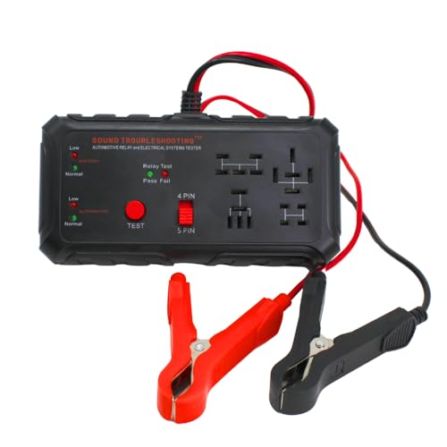
TESTS 4 & 5 PIN RELAYS: Quickly spot bad relays before they cause issues. This tool helps you confirm if your relays are firing correctly, removing the guesswork when diagnosing electrical issues. USA Patented.

EASY TO USE - The tester will automatically detect the pin position, the release time of the action, and the consistency of the relay in each test phase. If the tester lights up the green LED light, the relay is normal; if the red LED light is on, the relay is abnormal. USA Patented.
Step-by-Step: Measuring Coil Resistance
Before measuring coil resistance, you’ll need to properly prepare your multimeter and identify the correct terminals on the headlight relay. Set your digital multimeter to resistance mode, preferably the 200-ohm range for measurement accuracy. Locate pins 85 and 86 on the relay—these are your coil terminals. The relay casing typically displays a schematic for coil identification. Remove the relay from its socket to prevent circuit interference.
Place multimeter probes firmly on pins 85 and 86. Polarity doesn’t matter for resistance measurements. A functional headlight relay coil should read between 50 and 120 ohms. Infinite resistance (OL) indicates an open coil, while near-zero readings suggest a short. Both conditions require relay replacement. Clean corroded pins before testing to guarantee accurate contact and reliable readings. Document your resistance readings to confirm the operational status of the relay before deciding on replacement.

Connect the tool between the spark plug and the plug wire

QUICK DETECT: This ignition coil tester tool instantly detects ignition and spark plug problems. It can also test generators, fans, electric relays, emission gas control valves, fuel injectors, hall sensors, and more, making it ideal for detecting issues without removing components from the vehicle

Durable Material: This car ignition tester is made of plastic. Plastic materials have good impact resistance. Ignition testers made of these materials are more resistant to external shocks and vibrations, thus ensuring that they will work properly under daily use. Plastic material has a lower density and lighter mass, which makes the car ignition tester easy to carry and operate.
Step-by-Step: Testing Relay Contact Switching
After confirming coil resistance falls within acceptable parameters, you’ll need to verify the relay’s contact switching function to ascertain proper headlight operation. Set your multimeter to continuity mode and test terminals 30 and 87 in the inactive state—you shouldn’t detect continuity. Apply 12V power to coil terminals 85 and 86; listen for an audible click indicating actuation. While energized, retest terminals 30 and 87—continuity should now exist. For 5-pin relays, verify terminals 30 and 87a show opposite behavior. Testing Techniques include measuring voltage drop across energized contacts; readings should approximate battery voltage. Compare results against Relay Specifications from your service manual. Alternatively, swap the suspect relay with a known-good unit matching identical specifications to confirm switching behavior under actual load conditions. An overheating relay may indicate internal component damage and should be replaced immediately to prevent further electrical system issues.
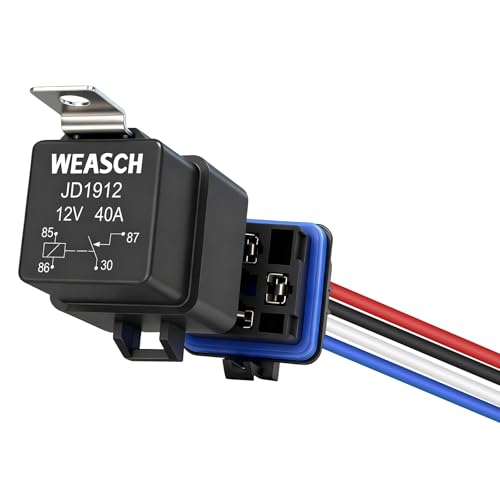
Rated Coil Voltage: 12V DC; Max. Rated Switching Current: 40A; Coil Power: 1.8W; Coil Resistance: 80 Ω

Integrated Diode: Each relay includes a built-in diode that suppresses induced voltage during switching, safeguarding your electrical components from potential damage.

Compatible with Volkswagen Type 1 [ Beetle / Bug ] 1967-79,
Advanced Tools for Professional Relay Testing
While multimeters and basic test procedures effectively diagnose most relay failures, dedicated automotive relay testers streamline professional diagnostics through automated detection and rapid pass/fail confirmation. These compact, cordless units test both 12V and 24V relays across common 4-pin and 5-pin configurations without manual setup. LED indicators display immediate results—green for pass, red for fail—while simulating real automotive electrical conditions to verify coil activation and contact switching. Advanced relay diagnostics include measuring contact closure timing, performing multiple test cycles for consistency checks, and detecting specific coil or contact faults. Professional testing equipment built with shock-resistant materials withstands demanding workshop environments while remaining compact enough for toolbox storage. Battery-powered operation eliminates vehicle power dependency, and universal pin adapters accommodate various relay footprints, simplifying advanced relay diagnostics across diverse automotive applications. The tester works by sending a small current through the relay coil to check for continuity in the switch contacts.

QUICKLY TEST RELAYS OUTSIDE OF THE VEHICLE to check coil and switch contact function

【2-in-1 Professional Diagnostic Tool】Battery & Relay Testing - Not just a battery tester. The KONNWEI KW371 integrates an advanced 12V/24V relay tester capable of diagnosing 4-pin and 5-pin automotive relays. Quickly identifies coil failures and contact wear without disassembling the entire fuse box—a must-have for mechanics and advanced DIYers.
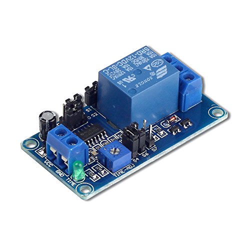
IMPORTANT NOTE: Please remove the jumper cap of S5 when controlling AC current or DC current voltages other than 12V, otherwise the module will be burned or will not work properly.