To replace a headlight connector, you’ll first disconnect the battery‘s negative terminal to prevent short circuits. Remove the headlight assembly to access the damaged connector, then cut back any melted wiring to expose clean copper. Strip 1/2 inch of insulation from each wire and attach a vehicle-specific pigtail using quality crimped connections—never solder, as it becomes brittle under vibration. Slide heat-shrink tubing over each joint, apply heat to seal, then reconnect everything and test both low and high beams to verify proper voltage and brightness throughout the entire circuit pathway.
Gather Your Tools and Materials
Successful headlight connector replacement begins with assembling a complete diagnostic and repair toolkit before you touch the vehicle. Proper tool selection starts with a multimeter for continuity checks, wire strippers sized for 18–14 AWG automotive gauges, and terminal release picks to extract damaged pins without cracking housings. You’ll need heat-shrink solder splice kits or insulated butt connectors matched to your repair method, plus dielectric grease for corrosion protection. Material compatibility is critical: source a vehicle-specific pigtail matching your bulb type (H11, 9005, etc.) and consider upgraded 14–16 AWG harnesses if heat damage is present. Don’t overlook safety glasses, gloves, and a fire extinguisher when using torch tools. Reference your service manual’s wiring diagram to confirm pinouts and connector orientation before starting. Always wear gloves during installation to prevent skin oils from contaminating electrical contacts and bulb surfaces. For cost-conscious DIY repairs, sourcing parts under $50 keeps expenses manageable compared to professional service fees.
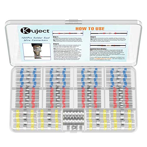
Time Saver: Solderless,crimpless, all you need is just a heat gun to finish the joint, much faster and easier than the old way

✔️【PREMIUM QUALITY】Thick copper barrel ensures strong secure crimping every time, providing minimal voltage drop, high current flow, and less heat. These will prevent short circuits and problematic wiring that inferior connectors are known for

[PREMIUM QUALITY] Thick copper barrel ensures strong secure crimping every time, providing minimal voltage drop, high current flow, and less heat. These will prevent short circuits and problematic wiring that inferior connectors are known for
Disconnect the Battery and Remove the Headlight Assembly
Before you open the connector housing or test circuit continuity, you must eliminate all current flow by disconnecting the battery—this single step prevents short circuits that can damage control modules, trigger airbag deployment, or cause arc burns when you handle exposed terminals. Observe safety precautions: wear acid-resistant gloves and safety glasses, remove jewelry, and work in a ventilated area. For battery disconnection, loosen the negative terminal clamp first using the correct-sized wrench, then move the cable away from metal surfaces. Next, disconnect the positive terminal. Wrap the red terminal with cloth to prevent accidental contact with metal surfaces. Secure both cables with insulated caps. Once power is isolated, locate and remove the fasteners securing the headlight assembly—screws, bolts, or clips—then carefully withdraw the housing to expose the connector for replacement. Take care to align any clips or screws back to their original positions to ensure proper fit and functionality.
Remove the Damaged Connector
Inspect the connector housing for thermal damage before attempting removal—melted plastic, charred pins, or green corrosion on terminals confirm the unit has failed and requires immediate replacement. When identifying damage, look for deformed shapes from electrical arcing or evidence of overheating that causes dim headlight operation.
Begin locating release mechanisms by finding the flat black tab or flap that locks the connector. Examine sides for small catches or wings securing the pins. Insert a flat screwdriver at the flap location, pushing toward the wire direction while lifting side catches with a thin tool. Pull the retaining tab to disengage the lock mechanism, then extract the connector straight out. For stubborn units, apply gentle leverage between the plug and headlamp face, ensuring you don’t damage surrounding seals. Proper connector alignment during reinstallation prevents future electrical failures and ensures secure contact between the headlight assembly and wiring harness.
Before cutting any wires, ensure headlights are off to prevent electrical shock or short circuits during the removal process.

Compatible With: This H13 / 9008 headlight connector pigtail wire harness fits Ford F-150 / F150 models from 2004 to 2019, designed to restore proper headlamp connectivity and eliminate issues caused by worn or corroded connectors.

Compatible with Polaris ATV UTV RZR Ranger Stator Connector Repair Kit
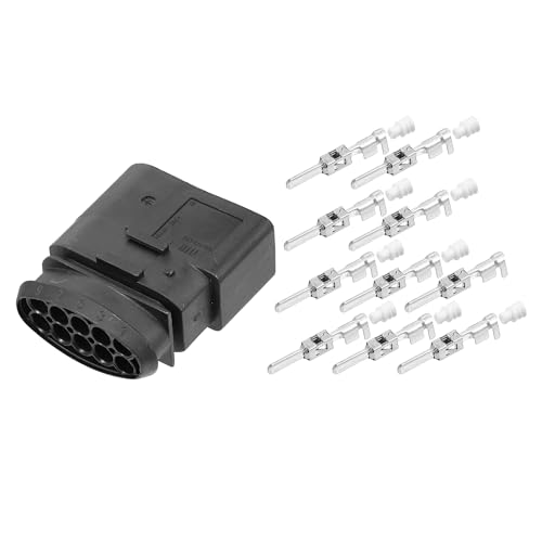
OE Number:1J0973835, Vehicle Waterproof Connector Plugs Set
Prepare the Wires for Splicing
With the old connector removed, prepare your replacement wires by measuring the exact length needed from the headlamp housing to where you’ll splice into the existing harness. Add three inches to accommodate routing adjustments and strain relief. Verify the wire gauge matches your application specifications—typically 10 AWG for high-draw circuits. Use wire strippers to remove 1/2 to 1 inch of insulation, exposing bare conductors without damaging individual strands. Before stripping, slide heat-shrink tubing over each wire for post-splice protection. Document the color coding of your existing harness: red/yellow indicates high beam, while maintaining proper polarity with red for positive and black for negative connections. Route wires away from heat sources and moving components to prevent insulation degradation and circuit failures. After splicing, apply a UV sealant coating to protect the connection from oxidation and environmental damage. For Nissan Rogue applications, LED bulb technology typically requires more careful connector selection than halogen alternatives due to sensitivity to electrical variations. Select weatherproof connectors if your headlight assembly is exposed to moisture or road debris.

【Heavy-Duty Construction for Harsh Environments】:Built with thicker copper and a heavy tin plating to combat corrosion where standard terminals fail. This robust design ensures stable electrical conductivity and long-term reliability in high-humidity, salty air, or under-hood environments, perfect for off-road vehicles, farm equipment, and coastal applications.

【Heavy-Duty Construction for Harsh Environments】:Built with thicker copper and a heavy tin plating to combat corrosion where standard terminals fail. This robust design ensures stable electrical conductivity and long-term reliability in high-humidity, salty air, or under-hood environments, perfect for off-road vehicles, farm equipment, and coastal applications.

Effective and Long Lasting Protection: innhom heat tube shrink has the advantages of good tightness, acid and alkali resistance, durable and anti-aging. Shrink wrap wire tensile strength: 14 Mpa. Dielectric strength: >20kV/mm. Elongation at break: >400%. Volume resistivity: >1.0× 10^14Ω.cm. Cold-resistant bending -22℉(-30 °C) × 1h without cracking. Use innhom heat shrink tubes instead of ugly and short-lived electric tape.
Crimp or Solder the New Connector
Once you’ve prepared the wires, you’ll need to choose between crimping and soldering to attach the new connector—and for headlight applications, crimping delivers superior results. Crimping advantages include creating an air-tight seal that protects against moisture and debris while forming a cold weld between the wire and terminal. This produces stronger connections that outperform soldering under vibration and mechanical stress. Soldering drawbacks become critical in automotive environments: the filler metal degrades over time, wicks up wire strands creating brittle zones, and weakens under high current loads. The solder also anneals the wire, reducing overall strength. For headlight circuits exposed to under-hood heat and constant vibration, proper crimping guarantees long-term reliability without the failure risks inherent to soldered joints. Using quality ratcheting crimpers ensures secure connections, as cheap tools often produce poor results that can compromise circuit performance.

Versatile Design: The waterproof automotive electrical connectors kit ncludes crimping pliers, two-in-one extractor tools, 1/2/3/4 pin automotive connectors plugs and sockets, compatible with 24-14 AWG wires for versatile automotive electrical applications
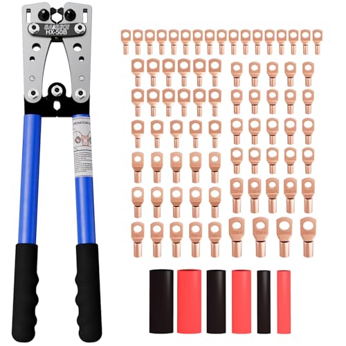
❀【Professional Battery Cable Crimper Kit】This battery cable lug crimping tool kit includes a ratchet wire crimper, 78pcs copper ring terminals, 110pcs heat shrink tubes—everything you need for battery terminal connections without buying extra wire connectors.

Versatile wire crimper set includes 1 ratchet crimper frame with 5 jaws, wire stripper and cross screwdriver. Satisfy the crimping needs of regular terminals, must have for electricians and DIYers.
Apply Heat Shrink Tubing for Protection
After completing the crimp connection, you must protect the joint from the harsh under-hood environment where headlight circuits operate. Slide the heat shrink tubing over the entire connector assembly, guaranteeing complete coverage of all exposed terminals. Apply medium heat from your heat gun, starting at the center and working outward to prevent air pockets. Watch for adhesive glue emerging from both ends—this indicates proper activation and sealing. The heat shrink provides critical waterproofing benefits by creating a barrier against moisture infiltration that could cause circuit failures. For maximum protection, overlap multiple tubes slightly when covering extended splice areas. This combination of mechanical crimping and thermal sealing guarantees your headlight connector withstands vibration, temperature cycling, and exposure to road contaminants. Allow the connection to cool completely before handling, as proper bonding requires adequate cooling time after heat application.
BIG COLLECTION – Totally 580pcs,11 specifications: 1/24"(80pcs),1/16"(80pcs),1/12"(100pcs),3/64"(30pcs),1/8"(60pcs),9/64"(30pcs),5/32"(70pcs),1/5"(30pcs),15/64"(20pcs),5/16"(20pcs),25/64"(60pcs).

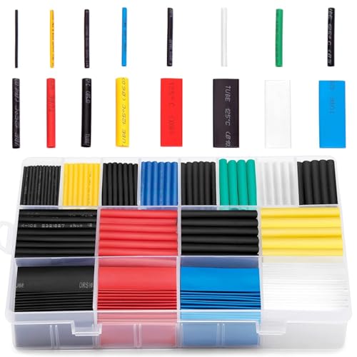
600PCS - 12 Sizes for Any Wire: No more mismatched shrink tubing! Eventronic 12-size assortment (1/24''-1/2'') heat shrink tubing covers everything from tiny electronics to thick cables. Stop wasting time hunting for the right fit—we’ve got you covered.

3:1 Heatshrink Ratio: The heat shrink butt connector has dual-wall shrinking tube and inside hot melt glue, providing a fully safe seal and wire corrosion. Its dual wall insulation seals against moisture corrosion, air leakage, and can be used underground
Reassemble and Test the Connection
Before energizing the circuit, carefully position the new connector by aligning each pin with its corresponding headlight bulb terminal. Match wire colors to their original positions, ensuring the longest wire reaches the farthest terminal. Twist copper strands tightly before sliding the connector onto bulb terminals until you hear an audible snap. Tuck excess wires into the housing, then secure with electrical tape to prevent movement during vibration. Route wires through the original loom, positioning them away from hot bulb surfaces. Replace the dust cap, ensuring full seating for waterproof integrity. Apply dielectric grease to the pin connectors to help prevent future melting issues. For long-lasting clarity and to protect connector contacts from oxidation, consider applying a UV-protective sealant after the initial installation. Perform final adjustments by inspecting for exposed wire and executing tug tests on all connections. Verify connection integrity matches the factory layout before testing circuit function.
Verify Headlight Operation
To confirm proper circuit completion and bulb functionality, energize the headlight system with the ignition in the “ON” position while the engine remains off. Rotate the headlight control switch through each position, verifying low beam activation first. Pull the high beam stalk to test filament switching in dual-filament bulb types. Observe headlight brightness from the front, confirming both assemblies illuminate with equal intensity—dimness indicates voltage drop or connector resistance. Check for flickering that signals intermittent contact at the replaced connector. Measure beam output against manufacturer specifications if photometric equipment’s available. Test parking lights separately by rotating the switch one detent before full activation. Ensure headlights are clean before testing, as debris can obstruct beam clarity and make it difficult to accurately assess connector performance. For stubborn residue or light scratches on the lens surface, consider using rubbing compound and polishing to restore optical clarity before evaluating connector function. If condensation appears inside the lens housing after connector replacement, use desiccant packets to absorb moisture without breaking the headlight seal. If either beam shows reduced output or fails completely, re-inspect connector terminals for proper seating and corrosion-free contact surfaces before concluding bulb replacement’s necessary.