To install a headlight assembly, start by disconnecting your vehicle’s negative battery terminal and removing any dust covers. Locate and extract the retaining bolts using appropriate socket wrenches, then carefully disconnect the wiring harness from the old assembly. Align your new assembly’s mounting tabs with the factory brackets, secure the bolts, and reconnect the electrical connections. Apply dielectric grease to prevent corrosion, test both high and low beam functions, then adjust the beam alignment using the vertical and horizontal screws for ideal performance and safety on the road ahead.
Gathering Tools and Preparing Your Vehicle
Before beginning any headlight assembly installation, gather the essential tools: flathead and Phillips screwdrivers for removing various fasteners, a socket wrench set with ratchet (particularly 8mm and 10mm sizes) for bolt removal, and pliers for handling clips and electrical connectors. Tool selection also includes work gloves, safety glasses, and a clean cloth to prevent component damage during handling. Ensure you have your new headlight assembly kit ready before starting the installation process.
For workspace organization, park your vehicle on a level surface in a well-lit area free of obstructions. Open the hood to access the headlight assembly’s rear components. Disconnect the negative battery terminal before starting work to prevent electrical shorts and voltage fluctuations that could damage sensitive LED components. If you’re working on larger vehicles, consider elevating them for improved access. Remove any dust covers or plastic rivets blocking the assembly area, noting their locations for reassembly. Using quality parts and performing timely repairs will ensure the safety and longevity of your headlight system.

SMALL BUT ENOUGH FOR YOU - Mini socket set Includes 10 Cr-V 1/4" Metric Sockets 4mm, 5mm, 6mm, 7mm, 8mm, 9mm, 10mm, 11mm, 12mm, 13mm on 10 collecting holders, each socket is labeled with the size which makes organizing easy. 1pcs 1/4" 24-teeth ratchet handle; 1pcs 4'' Extension bars.

Durable CR-V with Reinforced Walls:Our CR-V sockets deliver unparalleled reliability and safety by fundamentally eliminating the bursting risk common in thin-walled carbon steel models. This is achieved through the powerful synergy of superior chrome-vanadium steel and a robust, thickened inner wall design.

Value Pack: Set includes 12pcs 8mm sockets with 1/4"& 3/8" drive, 6-point, shallow/deep types(three of each type). Fits both shallow and deep fasteners, making it versatile for various repair and installation tasks.
Removing the Old Headlight Assembly
With your workspace prepared and battery disconnected, begin removing the old headlight assembly by opening the hood and locating the retaining hardware. Identify bolts or screws positioned on top, side, or across the assembly—certain models utilize Torx T30 fasteners. Use appropriate tools: wrenches for standard bolts, T30 Torx bits for specialized screws. Follow proper removal techniques by carefully extracting all hardware without dropping small components into the engine bay.
Once fasteners are removed, pull the assembly forward to expose electrical connectors. Apply safety precautions by using gloves when handling bulbs—avoid touching glass surfaces to prevent premature burnout and corrosion. Disconnect the halogen connector by pulling straight out. Twist turn signal sockets 45 degrees and remove. Turn the retainer ring counter-clockwise to remove the bulb sockets from the old headlight. Most headlight replacement procedures can be completed in 10-15 minutes with the right tools and preparation. Confirm no remaining fasteners before complete extraction to prevent assembly damage.
Installing the New Headlight Assembly
Once you’ve removed the old headlight assembly, position the new unit by aligning its mounting tabs with the factory brackets on your vehicle’s frame. Slide the assembly inward until the tabs engage securely. Install the top mounting bolts using your socket wrench, then secure with the retainer ring by rotating clockwise until locked. Connect the wiring harness per the diagram—plug in connectors for low beams, high beams, and turn signals firmly. When selecting bulbs, match part numbers precisely; the higher number typically indicates the low beam. Insert bulbs by aligning tabs and turning clockwise until they click. Consider the brightness levels measured in lumens when choosing replacement bulbs to ensure optimal nighttime visibility and safety. For added protection, apply dielectric grease on connections to prevent moisture and corrosion in the electrical connectors. For aftermarket units improving visibility with halos or DRL strips, follow manufacturer wiring instructions and use waterproof connectors. Reinstall dust covers tightly. After completing the installation, test that the automatic lighting controllers activate properly to ensure all safety features are functioning correctly.

KIT CONTENTS: Each headlight restoration kit includes (8) Step 1 Oxidation Removing Wipes, (1) Step 2 Sanding Kit, and (2) Step 3 Ceramic Coating Wipes

KIT INCLUDES: 1 - Disc Pad Holder, 3.25 in (8,2 cm) 6 - 3M Gold Sanding Discs 500 Grit, 3 in (7,6 cm) each 4 - 3M White Finishing Discs 800 Grit, 3 in (7,6 cm) each 1 - 3M Trizact Refining Disc 3000 Grit, 3 in (7,6 cm) 2 - 3M Quick Headlight Clear Co

KIT INCLUDES: 1 - 3M Trizact Refining Disc 1000 grit, 3 in/7.6 cm 1 - 3M Trizact Refining Disc 3000 grit, 3 in/7.6 cm 2 - 3M Quick Headlight Clear Coat Wipes 1 - Foam Pad with 3M Hookit Attachment, 3 in/7.6 cm 1- Disposable Glove
Testing Your Headlight Functions
After completing the installation, verify proper headlight operation through systematic electrical and functional tests. Set your multimeter to volts mode and activate the headlights. Test the bulb socket terminals—you should read approximately 12 volts, confirming adequate power supply. Next, switch to ohms mode and disconnect the bulb from its harness. Touch the multimeter probes to the bulb base contacts; low resistance indicates an intact filament. For headlight maintenance verification, use a circuit tester at fuse terminals—it’ll glow when power’s present. Check both low and high beam functions sequentially. A clicking sound when the headlights engage indicates the relay is engaging properly. Wear protective gloves when handling electrical components to prevent injury and avoid damaging sensitive parts. This testing protocol guarantees your bulb selection delivers proper illumination and validates the complete electrical circuit integrity. Document voltage readings for future troubleshooting reference.

This Relay Bypasses Switches is great for electrical diagnostics, Simply plug it into the location of the fuel pump relay and it will directly control the fuel pump circuit. Saves a ton of time

Powerful: This relay bypass switch controls the fuel pump independently of the "key on/off" system, Simplifying fuel injection testing
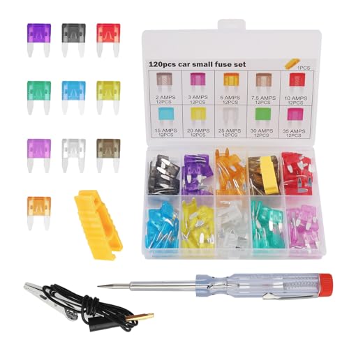
All-in-One Fuse Solution: You will receive a comprehensive set of 120 car fuses across 10 different amperage ratings (ranging from 2A to 35A), with 12 of each type. The kit also includes 1 fuse tester and 1 fuse puller, providing everything you need for complete electrical system maintenance and replacements
Aligning Your Headlight Beams
Proper beam alignment guarantees your newly installed headlight assembly illuminates the road effectively without blinding oncoming drivers. Park on level ground with correct tire PSI, then position your vehicle close to a flat wall. Measure and mark vertical lines at each headlight center, connecting them horizontally with a level. Add horizontal tape 2 inches below the headlight center height. Reverse exactly 25 feet from the wall, maintaining straight alignment. Locate the vertical and horizontal adjustment screws under the hood. Adjust each headlight so the beam intensity focuses just below the horizontal tape mark at the X-Y intersection. Turn adjusters in quarter-turn increments until achieving proper headlight adjustment. If your headlights have combined low and high beams, align the low beam first to ensure accurate high beam positioning. Remember that the adjustment screws are typically located at the back of the headlight housing and accessible from the engine bay or behind the headlight assembly. After achieving proper alignment, applying a clear coat or UV sealant will protect your headlight assembly from oxidation and yellowing over time. Conduct a night road test to verify adequate illumination without excessive glare.