To wire daytime running lights, you’ll first disconnect your vehicle’s battery and identify an ignition-switched power source. Install a 12V automotive relay with terminal 86 connected to the ignition circuit, terminal 30 to battery positive through an inline fuse, and terminal 85 grounded to chassis. Route the switched output (terminal 87) to your DRL units, ensuring proper gauge wire for minimal voltage drop. Integrate a headlight override circuit so DRLs deactivate when you switch on your main beams. The following sections cover relay sizing, circuit mapping, and thorough troubleshooting techniques.
Understanding Daytime Running Light Systems and Types
When you turn your vehicle’s ignition, daytime running lights (DRLs) activate automatically through a dedicated circuit that operates independently from your main headlight system. This DRL functionality overview reveals how the system draws power from your vehicle’s electrical supply and deactivates when you engage your headlights, preventing redundant illumination.
You’ll encounter different DRL types during installation. LED DRLs offer 50,000-hour lifespans with minimal power consumption, while halogen units provide under 2,000 hours. Low-beam configurations reduce voltage to existing headlights, and dimmed high-beam systems regulate current for decreased intensity. Standalone units mount separately on your bumper. Each type requires specific wiring approaches, with LED systems demanding precise voltage regulation and halogen setups needing appropriate resistor networks to prevent electrical issues. These systems are designed to enhance vehicle visibility during daytime driving conditions, making your vehicle more detectable to other road users. To maintain optimal performance, consider protecting your DRL lenses from oxidation through protective clear coats similar to headlight preservation methods.
Legal and Safety Considerations Before Installation
Before connecting any wiring harness, you must verify that your aftermarket DRL installation complies with Federal Motor Vehicle Safety Standard No. 108 §571.108, which permits—but doesn’t require—DRLs on passenger vehicles, trucks, and buses. Legal implications include ensuring your LEDs emit only white, yellow, or amber light—never color-changing modes on public roads. Your circuit must deliver photometric output meeting S5.5.11(a)(1) minimums without exceeding maximum brightness thresholds that cause glare. Safety guidelines demand understanding that DRLs don’t substitute for headlights under reduced visibility conditions. States like Tennessee and North Carolina enforce “wipers on, lights on” laws requiring full headlights during rain, regardless of DRL operation. Many states have laws mandating the use of headlights during daytime under specific conditions such as reduced visibility from rain, fog, or snow. Aftermarket LED installations should be DOT-approved assemblies to ensure compliance with vehicle code regulations and avoid failed inspections. While U.S. federal regulations do not mandate DRLs for commercial vehicles, Canada requires DRLs on all new vehicles when headlights are not in use, with legislation updated in 2021 to enhance overall lighting standards. Verify local regulations before installation to avoid fines or failed inspections.
Choosing the Right Power Source for Your DRLs
The electrical foundation of your DRL system depends critically on selecting the proper power source, as each method delivers distinct voltage characteristics, activation timing, and current capacity. Battery direct connection provides constant 12V for high-draw LED modules but requires inline fusing and exposes circuits to cranking fluctuations. Ignition-switched power prevents parasitic drain by activating only when your key’s in ON position, drawing minimal current like 60mA through accessible dashboard taps. Engine running signals via D+ alternator output guarantee operation solely during engine operation, ideal for dipped headlamp configurations. Headlight circuit integration enables automatic dimming when you activate main beams. When evaluating power source options, consider wiring pros and cons: battery connections offer reliability but risk drain, while switched sources provide protection against dead batteries through controlled activation sequences. Many modern vehicles include perimeter lighting systems that automatically control lighting behavior based on vehicle state and user settings. For vehicles equipped with HID or LED headlight systems, ensure your DRL configuration is compatible with HID and LED technologies to maintain proper lighting balance. Installing LEDs instead of standard bulbs significantly reduces power consumption, with LEDs drawing only milliwatts compared to the 30-40W required by conventional incandescent bulbs.

【High-quality materials】The light bar is made of high-quality silicone and LED, waterproof and durable, and has a long service life. High quality can not only provide a safer guarantee for your life, but also high quality materials can prolong the service life of the product.

LEADTOPS,DIY ultra thin,easy to install:connect the positive and negative wires to any of your vehicle power

❤️ High brightness --- Imported high-purity LED high-power light source five lamp beads structure design;
Essential Wiring Components and Hardware You’ll Need
Once you’ve identified your power source, gathering the correct wiring components and hardware becomes your next priority—choosing substandard parts or incorrect wire gauges will compromise both DRL performance and vehicle electrical safety. Component selection starts with a purpose-built DRL harness featuring an integrated relay (4- or 5-pin automotive type) and inline fuse holder rated for your load plus 25% margin. Use 12–14 AWG wire for higher-current assemblies to maintain voltage drop below 0.5 V. Harness customization demands weatherproof connectors (Deutsch or IP67-rated), insulated crimp terminals, and dual-wall heat-shrink tubing for exterior runs. Add quick-disconnect pigtails for headlight-switched logic, Schottky diodes to prevent backfeed, and ring terminals with star washers for reliable chassis grounding at terminal 31 locations. Before finalizing your installation, verify all wiring connections and test functionality to ensure proper DRL operation. Budget approximately $20 for parts when sourcing components online from major retailers.

[OEM Part Number:] 15306157 19258649 LS94; Please Check the OEM Part Number and Make Sure Your Part Number Matches this Part Number Before Buying

【Compatible Bulbs】Our Daytime Running Light Socket Replacement for 3156 3056 3456 4156 3057 3155 3357 3457 3757 4057 4114 4157 Bulbs The pigtail wire socket for daytime running lamp turn signal/brake/tail lights.|| Please Double Check The Year Make Model To Make Sure What You Need Before Ordering Thank You!
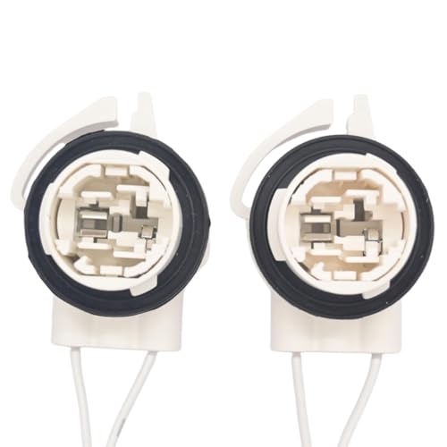
[Replaces Part Number:] 15306157 19258649 LS94; Please Check the OEM Part Number and Make Sure Your Part Number Matches this Part Number Before Buying!
Planning Your DRL Circuit and Relay Configuration
After you’ve assembled your components, mapping the relay logic and power-distribution paths determines whether your DRL installation will operate reliably or introduce electrical faults and safety hazards. Choose an ignition-switched input for relay activation methods—ACC or IGN circuits—to energize the coil automatically. Size the relay for 30% above maximum DRL current and route a dedicated high-current feed from the battery if your lights draw beyond 3–5 A. Employ proper circuit grounding techniques: establish a solid chassis or battery-negative ground point, using star-grounding to eliminate ground loops. Position the fuse close to the power source to limit fault current, and verify wire gauge matches relay and fuse ratings. Include a flyback diode across the relay coil to suppress voltage spikes that can damage electronic modules. Configure the relay’s normally-open contact to keep DRLs continuously on during ignition, ensuring the lights receive stable power whenever the vehicle is running. Modern DRL systems often integrate with the vehicle’s existing headlight switch to provide seamless automatic operation.

【12V 40A PEAK CAPACITY】Rated for 12V DC systems with a 40A max peak switching current (1.8W coil power, 80Ω resistance). Always keep your continuous loads 10% to 15% below the rated value to ensure maximum electrical safety and relay longevity

Compatible with 2010-2013 Chevy Camaro LS LT (halogen trims ONLY)

Compatible with 2010-2013 Chevy Camaro LS LT (halogen trims ONLY)
Step-by-Step Relay Wiring and Pin Connections
With your circuit plan finalized, begin the physical wiring by identifying the four primary terminals on your automotive relay. Standard 4-pin relay types use terminal 85 for coil ground, 86 for coil power from ACC switched sources, 30 for constant 12V battery input with inline fuse protection, and 87 for switched output to your DRL positive. Five-pin configurations add terminal 87a for normally closed circuits if alternate switching is required. Verify your pin configuration using a test light: with ignition on, you’ll detect power at pins 85 and 87; key off shows power only at 87. Connect terminal 30 to battery positive through an appropriately rated fuse—30A green, 25A white, 20A yellow based on load requirements. Ground terminal 85 securely to chassis, ensuring reliable relay operation. Avoid using relays that control critical vehicle functions such as ECU or ignition systems to prevent interference with essential operations.

Upgraded Version - Automotive relays built in fuse socket included 30A blade fuse with heavy duty 14AWG wires for main contact. no need of a separate fuse holder, saving space and money. 4-Pin SPST (Single Pole Single Throw) Relay.

High switching capability: Normally open 40A/14V DC and normally close 30A/14V DC. Suitable for Nilight LED light bar wiring harness kit
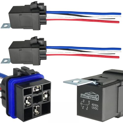
Note: Pin 86 connects to the positive pole, and Pin 85 connects to the negative pole
Installing and Routing the DRL Wiring Harness
Before routing any wiring harness components, disconnect your vehicle’s battery at the negative terminal to eliminate short-circuit risks during installation. Identify your vehicle’s wiring harness access points by popping out the driver’s side marker light and unplugging existing connectors. Carefully slice open the headlamp and side marker harness sheathing using a sharp knife, exposing the wires you’ll tap into.
Route relay wires through the engine bay, snaking them through black tubes and firewall openings. Pull wires to length from your chosen fuse box terminals, then run them through the front bumper area. Connect left and right harnesses using shrinkwrap for secure wire management. For ideal relay placement, mount it using existing kick panel bolts where it remains accessible yet protected from interference. Always verify that your completed installation meets DOT compliance standards for safety and legality. Keep wiring organized during installation to prevent tangling and ensure a clean, professional-looking setup.

【Compatible with】 Fit for Tayota, S.ubaru, Honda, Lexus, Fiat, Chrysler vehicles that upgrade halogen DRL/high beam bulbs to 9005 LED, causing DRL not working properly or flickering. Designed for PWM dimming systems (measurable by multimeter). Please refer to the fitment picture for specific models

【Product Specifications】: The car tail light socket set includes 4pcs 3157 sockets, each measuring 5.66 inches. These sockets are suitable for replacing turn signals, brake lights, tail lights, and daytime running light sockets. Please check in advance that the bulb socket model and size are compatible with your vehicle.
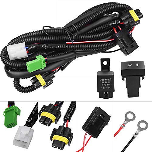
Good For Replacement fog lamps, Add-on fog lights, HID lights, LED daytime running lights, Driving lights, LED work lights, Off-road lighting kit
Testing Your DRL System and Headlight Integration
Once you’ve completed the physical installation and secured all connections, verify your DRL system operates correctly through systematic electrical testing. With your engine running and headlights in auto position, measure voltage on the high beam wire—you’ll need 6-7 volts for proper operation. Test sensor calibration by observing activation during daytime conditions; your ambient light sensor should trigger DRLs automatically when detecting sufficient daylight. For integration verification, confirm DRLs deactivate when you switch on your headlamps. Check continuity across brown wires to the fuse box if lights fail. Place your vehicle in neutral with the parking brake engaged, then slowly release the foot brake while observing your reflection in nearby glass windows to confirm proper beam pattern and intensity. Quality DRL performance depends on selecting bulbs that meet DOT and ECE regulations to ensure your system delivers superior visibility and safety. When choosing replacement bulbs, consider halogen, LED, and HID technologies to optimize your DRL output and longevity. Ensure your DRLs exhibit a blur of light without a concentrated hotspot, which distinguishes them from standard headlamps during operation.
Troubleshooting Common DRL Wiring Issues
When your DRL system fails to operate correctly, begin diagnosis at the fuse panel since a blown fuse immediately points to downstream shorts or component overloads rather than simple age-related failure. Next, perform relay troubleshooting by testing the DRL relay’s operation and contact continuity. Measure voltage at each lamp socket with ignition ON to confirm power delivery; absence indicates upstream faults in the relay, BCM, or harness. Test ground continuity at both lamps, as high-resistance grounds cause dimming or single-side failure. Inspect for wiring corrosion at socket contacts and connectors, especially in front harness areas exposed to moisture and road salt. Check for chafed insulation from improper routing that creates intermittent shorts. Swap known-good bulbs to isolate component versus circuit faults efficiently. Additionally, verify the ambient light sensor is not obstructed by items on the dash, as blockage can prevent proper DRL activation.
Maintaining Your DRL System for Long-Term Reliability
A properly maintained DRL system delivers consistent performance and extends component service life beyond manufacturer baseline expectations. Follow these DRL maintenance tips to maximize reliability: conduct monthly inspections examining lenses for cracks, fogging, or moisture ingress while verifying electrical connections remain sealed. Clean lenses using mild soap and microfiber cloths—avoid ammonia-based products that degrade plastics. For LED lifespan extension, guarantee cooling fins stay dust-free by using compressed air quarterly, and verify proper ventilation during summer months. Check mounting hardware security and wiring for corrosion or wear during routine inspections. Maintain the 200–800 lumens brightness threshold per OSHA standards. Apply UV protectant to parked vehicle lenses, and always activate lights after engine start to prevent voltage spikes that compromise circuit integrity. When inspecting your DRL system, use masking tape to mark beam positions on a wall to verify proper alignment and positioning. Ensure your vehicle is parked on a level surface during maintenance to accurately assess beam alignment and mounting integrity. Document all maintenance activities and issues discovered during inspections to ensure regulatory compliance and facilitate timely resolution of emerging problems.