To aim projector headlights, park your vehicle on level ground exactly 25 feet from a flat wall. Verify proper tire pressure and remove excess cargo. Mark the headlight optical centers’ height on the wall, then turn on your low beams. Using a Phillips screwdriver, adjust the vertical screw until the sharp cutoff line sits at or slightly below your horizontal reference mark. Next, adjust horizontally so the brightest beam portion falls 2-4 inches right of center. This guide provides complete step-by-step instructions for professional-grade alignment.
Gather Your Tools and Materials
Before adjusting your projector headlights, you’ll need to assemble specific tools that guarantee precise beam alignment according to DOT standards. Your tool selection should include a long Phillips head screwdriver for most adjustment screws, though some housings require Torx bits or specialized headlight adjustment keys. Material preparation involves gathering measurement devices: a measuring tape for determining headlight center height, a level for straight markings, and masking tape to mark horizontal reference lines. You’ll need marking supplies including chalk and dry erase markers for temporary wall notations at the 25-foot distance marker. Ensure your tires are properly inflated to recommended levels before beginning the aiming process. Position your vehicle on a level surface about 25 feet from a wall to create an accurate testing environment. Specialized equipment like a laser pointer enables accurate centering of LED matrix or parabola configurations. Remember that HID bulbs work best with projector-style headlights to ensure proper light distribution during the aiming process. Consult your owner’s manual to identify vehicle-specific adjuster locations, and review DOT guidelines requiring a 2-inch drop for headlights mounted above 36 inches.

STRENGTH AND DURABILITY: Made of heat-treated alloy steel
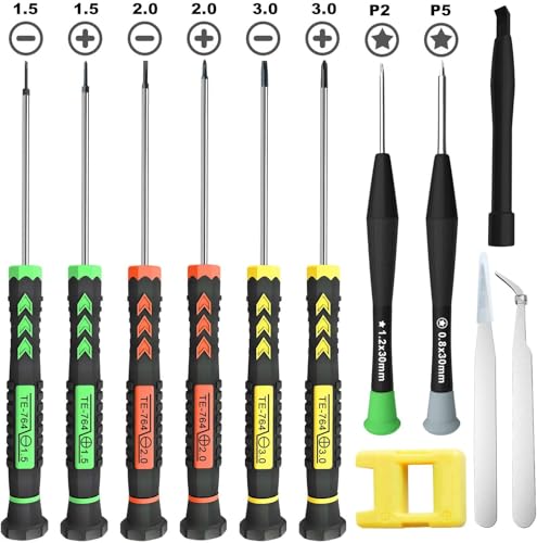
[Package Includes] – 1 x 3.0 Flathead Screwdriver, 1 x 2.0 Flathead Screwdriver, 1 x 1.5 Flathead Screwdriver, 1 x 3.0 Phillips Screwdriver, 1 x 2.0 Phillips Screwdriver, 1 x 1.5 Phillips Screwdriver, 1 x Pentalobe 2 Screwdriver, 1 x Pentalobe 5 Screwdriver, 1 x Helper Stick, 2 x Tweezers, 1 x Magnetizer & Demagnetizer Tool

STRENGTH AND DURABILITY: Made of heat-treated alloy steel
Choose the Right Location for Headlight Aiming
Because accurate headlight aiming depends on precise beam geometry, you’ll need to select a location that combines a flat vertical surface with level ground and controlled lighting. Your site selection should include a white or light-colored wall at least 25 feet from where you’ll park, guaranteeing the surface is smooth and wide enough to accommodate both headlight centerlines plus 12–24 inches. Verify the pavement is level using a spirit level—any pitch or roll will compromise vertical aim. For ideal lighting conditions, work at dusk or in a shaded area where ambient light won’t mask the beam cutoff. Avoid locations with glare sources behind your aiming position or intermittent illumination from passing traffic. Confirm you have at least 25 feet of clear, unobstructed space to allow proper beam pattern evaluation. This controlled environment guarantees repeatable results that meet DOT regulatory testing standards.
Position Your Vehicle Properly
Proper vehicle positioning establishes the foundation for accurate headlight aim measurements and regulatory compliance. You’ll need to position your vehicle on a flat, level surface with tires inflated to manufacturer specifications. Remove excess weight and fill your gas tank to maintain consistent vehicle height. Mark a point exactly 25 feet perpendicular from the wall—this DOT-standard distance guarantees accurate aiming techniques. Align your headlights with this mark, verifying the vehicle sits square to the wall without angular deviation.
For proper vehicle alignment, verify you’re pulled back in a straight line from your initial reference marks. Check that your headlights shine directly at the wall, creating the cross-section view necessary for beam alignment verification. This perpendicular positioning prevents measurement errors that compromise aiming accuracy. Using masking tape to mark the horizontal and vertical centers of each headlight beam on the wall helps establish precise reference points for comparison. Measure and mark the center of the projector to establish your vertical reference point for proper beam height adjustment. After achieving proper alignment, apply a protective coating to your headlight lenses to maintain clarity and prevent oxidation that could interfere with beam projection accuracy.
Prepare Your Vehicle for Accurate Aiming
Accurate headlight aiming requires your vehicle to match the precise conditions under which it operates daily. Begin with a thorough suspension check, ensuring no sag or damage affects ride height. Proceed with tire inflation to manufacturer-specified PSI, verifying all four tires match exactly. Remove heavy items from the trunk unless you regularly carry cargo. Fill engine oil and coolant to recommended levels, as fluid deficiencies alter vehicle stance. For air suspension systems, maintain at least 90 PSI throughout the procedure. Position your vehicle on a level surface, confirmed with a carpenter’s level. If you typically drive with passengers, simulate that weight with a 55 kg occupant in the driver’s seat. Inspect headlight assemblies for damage, loose mounting, or inoperable adjustment screws before proceeding. Ensure the vehicle is positioned 25 feet away from a wall to establish the proper distance for marking and adjusting the headlight beams. Use bubble levels if available for more precise alignment during the aiming process.

Give your GM 1500 the perfect blend of performance, protection, and style from Rough Country.

COMPATIBLE VEHICLES: Does not fit 2014-2018 "Denali" models; Does not fit 2007 "Classic" models)/NOT fit ZR2, TrailBoss, AT4/"MagneRide" models,2019-2024 new body style 4WD models.

Give your Silverado/Sierra the Perfect Blend of Performance, Protection, and Style from Rough Country.
Measure and Mark Headlight Height on the Wall
With your vehicle properly positioned and suspension verified, locate the aiming dot or dimple molded into each projector headlight lens—this mark indicates the optical center of the beam assembly. Use a tape measure for distance measurement from ground to this center point on both headlights separately. Turn on your low beams and position horizontal masking tape on the wall at the recorded height directly in front of each assembly. Apply the DOT offset rule: headlights exceeding 36 inches require a 2-inch downward adjustment from center height. Mark this reference line with a pen, ensuring it remains level across the wall surface. This horizontal line establishes your headlight alignment baseline, with the “H” designation indicating low beam height for proper cutoff verification during adjustment. H11 bulbs are typically used for low beam applications and produce a warm light ideal for visibility control. Proper beam patterns and cutoff lines are essential for maintaining compliance with lighting regulations while ensuring optimal visibility. Ensure the vehicle remains parallel to the wall throughout the measurement process to maintain accurate reference points for adjustment.
Measure and Mark Headlight Width on the Wall
Establishing lateral reference points begins by confirming your vehicle sits perpendicular to the wall, with the chassis centerline aligned to a vertical reference mark you’ve placed at the wall’s midpoint. Measure the horizontal distance between projector lens centers (or manufacturer aiming dots) to the nearest 1/8″, repeating twice for verification. From the wall centerline, measure outward half the recorded headlight spacing, then apply vertical tape strips at each headlight center location using precise marking techniques. Verify tape application creates plumb lines extending 18–24″ vertically, verified with a level. Ensuring proper aiming of your projector headlights is legally mandated to prevent dazzling other drivers and maintain compliance with safety regulations. Label each vertical tape “L” and “R,” recording lateral distances beside each mark. These vertical references define the horizontal aim corridors where beam cutoffs will align during final adjustment at your chosen working distance. Proper beam pattern alignment requires matching your LED bulbs to the factory bulb type to maintain correct reflector function and achieve the desired cutoff line.
Turn On Your Low Beams and Begin Adjustments
Before activating your headlights, verify the vehicle sits level with tires inflated to specification, fuel tank at least half full, and no unusual cargo affecting suspension height. Switch on low beams only—high beams alter cutoff characteristics and mislead adjustments. Observe the sharp horizontal cutoff typical of projector units; note any asymmetry between left and right beams relative to your wall centerline marks. Mark current beam edges with masking tape to establish a baseline. Use horizontal adjusters to shift the high-intensity zone slightly right of each projector’s vertical centerline, preventing oncoming glare. Make incremental turns—small changes magnify at distance. For vertical alignment, adjust so the cutoff’s brightest portion meets your horizontal reference line, ensuring proper safety reflecting beams without adjusting headlight brightness beyond factory specifications.
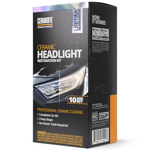
KIT CONTENTS - Each headlight restoration kit includes (8) Step 1 Oxidation Removing Wipes, (1) Step 2 Sanding Kit, and (2) Step 3 Ceramic Coating Wipes.

【Unique Angel Eyes Shrouds】3.0 Inch angel eyes switchback Shrouds comes with turn signal feature,unique appearance makes your car look more attractive.
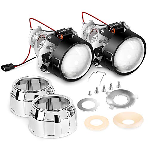
H1 mini projector kits (low/high beams), fit in tight spaces for quad retrofits or fog lamp upgrade
Adjust the Vertical Beam Pattern
Once you’ve marked your reference lines and verified vehicle ride height, locate the sharp horizontal cutoff line projected onto the wall—this cutoff represents the top edge of your low beam pattern and serves as the primary vertical aiming reference for projector headlights. Find the vertical adjustment screw on top of the headlamp housing and use the appropriate tool to make small incremental turns. Clockwise typically raises the beam; counterclockwise lowers it. Observe the cutoff movement after each adjustment, aiming until the top of the intense beam area sits at or slightly below your horizontal tapeline—commonly 2 inches below at 25 feet. Repeat this vertical adjustment for both headlights to achieve consistent beam alignment. Confirm left and right cutoffs form one continuous horizontal line at the target height for peak visibility and glare control. If access is restricted, you may need to pull back the fender to reach the aiming adjusters.

1 unit of front headlight adjustment screw driver tool ONLY for 2018-2022 JL.

Applications: Audi A4 8K, A6 4G, A5 8T; Volkswagen Passat B8, Touarag II.

Shaft Length: 300mm
Adjust the Horizontal Beam Pattern
With vertical alignment complete, horizontal beam adjustment guarantees your projector headlights direct the most intense portion of the light pattern to the right of the vehicle centerline, away from oncoming drivers. Locate the horizontal adjusters on your headlamp assemblies—note that not all vehicles include them. Turn adjusters in quarter-turn increments using a Phillips screwdriver while monitoring the wall pattern. Position the brightest beam core 2 to 4 inches right of your vertical centerline tape. The right beam edge should align at the horizontal tape marking, while the left edge sits 3 inches below. If horizontal adjusters aren’t present, shim the housing to achieve proper beam alignment. Avoid power tools during adjustment to prevent internal gear damage. Both headlights must target the same horizontal plane for balanced illumination. For vehicles equipped with ambient light sensors, you may need to adjust settings to ensure consistent beam patterns regardless of surrounding light conditions. This symmetrical adjustment reduces glare for oncoming vehicles while providing adequate road illumination.
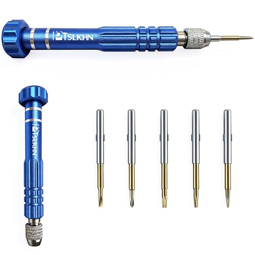
[Must Have for All Technicians] -2.0, +1.5, torxT6, torxT5, star0.8 bits in one MINI SCREWDRIVER SET
Different Size: Our tiny screwdriver set includes11 different screwdrivers. 3 Phillips head screwdriver sizes (#00, #0, #1) and 6 flat head screwdriver sizes (1.2mm, 1.4mm, 1.8mm, 2.0mm, 2.4mm, 3.0mm), 1 Awl; 1 Magnetic. 11 kids of sizes meet your multi kinds of needs in daily life, such as table battery covers off for toys and replace the batteries

11 DIFFERENT SIZES: Our mini screwdrivers set includes 3 screwdriver sizes (#00, #0, #1) and 6 flat head screwdriver sizes (1.0mm,1.2mm,1.4mm, 1.8mm, 2.4mm, 3.0mm), 1 Awl; 1 Magnetic. 11 kids of sizes meet your multi kinds of needs in daily life, such as table battery covers off for toys and replace the batteries
Verify and Fine-Tune Each Headlight
After completing individual headlight adjustments, activate both low beams simultaneously to verify unified beam performance. Observe how both projectors create beam overlap in the center, forming a single, distinct step pattern. Check that cutoff alignment matches your marked horizontal line “M2” at the 25-foot distance. The top edge of the intense beam section should remain at or below this reference line. If you notice discrepancies, make incremental adjustments using the vertical adjustment screws. Turn slowly—quarter-turn increments prevent over-correction. Block each headlight alternately to isolate any remaining height variations. Once both cutoffs align precisely with the horizontal tape and create proper beam overlap centrally, test your high beams. They should center on the horizontal line. Misaligned headlights can create dangerous driving conditions by reducing your visibility or blinding other motorists. Consider measuring brightness levels in lumens to ensure your projector headlights meet optimal performance standards. Different headlight bulb technologies such as halogen, LED, and HID options can affect your projector’s overall brightness and beam quality. Finally, recheck alignment with normal cargo loading conditions.