
You’ll find headlight adjustment screws in three primary locations: on top of the headlight housing accessible from the engine bay for vertical control, along the side near the fender for horizontal alignment, or underneath through the wheel well opening. Each screw operates independently—vertical adjusters control beam pitch while horizontal screws shift the pattern laterally. Your specific vehicle’s configuration may vary by manufacturer, model year, and housing type, so consulting your owner’s manual guarantees you’re identifying the correct adjustment points for safe, precise beam alignment.
Common Mounting Positions on the Headlight Housing
Headlight adjustment screws typically occupy one of four mounting positions on the headlight housing: top, side, bottom, or center lens. You’ll find vertical adjustment screws positioned on top of the housing, accessible from your engine bay. Side-mounted screws control horizontal alignment for left-right movement. Bottom adjusters appear on certain models, reachable through wheel wells or splash shield slots. Central positions near the lens cap consistently handle height adjustment regardless of housing design.
Common misconceptions suggest all headlights share identical placement—they don’t. Manufacturer-specific configurations vary greatly. Modern LED headlight upgrades may have different adjustment screw positions compared to standard halogen housings due to their cooling system efficiency and internal component layout. Proper adjustment techniques require identifying your exact screw locations before attempting alignment. Top adjusters typically use Phillips screwdrivers, while side mechanisms may need socket or Torx drivers. Always verify adjuster type and position to prevent housing damage during adjustment procedures. Applying silicone lubricant to the screws protects them during adjustment and prevents future binding. Testing your alignment by driving at night allows you to confirm proper beam positioning before finalizing adjustments.
Identifying Adjustment Fastener Types and Interfaces
Modern adjustment mechanisms employ distinct fastener interfaces that directly affect your tool selection and adjustment procedure. You’ll encounter three primary fastener types: bolt-head designs accessible from the rear, notched plastic clips with teeth requiring screwdriver engagement from the top, and threaded screws feeding directly into adjustment gears. The adjustment interfaces vary by manufacturer—some models utilize bolt heads for wrench access, while others like the Toyota Sequoia exclusively require screwdriver operation. BMW applications feature vertical alignment screws, whereas domestic vehicles often employ gear-driven systems where screwdriver rotation direction opposes the intended movement. Metal and plastic construction materials, including natural and white nylon variants, determine durability and torque requirements. For vehicles equipped with bi-LED headlight assemblies, ensure that any adjustment procedures account for the specific mounting requirements of these advanced lighting systems. Proper beam alignment adjustment after installation ensures optimal lighting performance and visibility. GM vehicles from 1962 onwards utilize standardized adjustment screw configurations with common thread sizes like 1/4-28. Always identify your specific interface before beginning adjustments to prevent fastener damage.

Headlight adjust kit for 78-81. Complete kit with all push-in nuts, screws and correct springs.
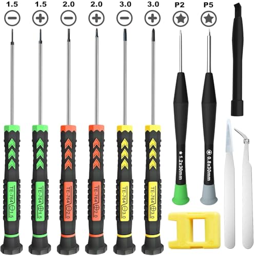
[Package Includes] – 1 x 3.0 Flathead Screwdriver, 1 x 2.0 Flathead Screwdriver, 1 x 1.5 Flathead Screwdriver, 1 x 3.0 Phillips Screwdriver, 1 x 2.0 Phillips Screwdriver, 1 x 1.5 Phillips Screwdriver, 1 x Pentalobe 2 Screwdriver, 1 x Pentalobe 5 Screwdriver, 1 x Helper Stick, 2 x Tweezers, 1 x Magnetizer & Demagnetizer Tool

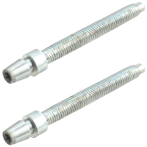
New correct style headlight adjuster set for your classics. Kit includes; 4 plastic nut retainers, 4 long adjuster screws, and 2 tension springs. Premium quality design and construction. Compatible with: -1967-1973 Camaros -1970-1972 Monte Carlos
Understanding Vertical vs. Horizontal Adjustment Controls
Before you begin turning adjustment screws, you must distinguish between vertical and horizontal controls because each axis serves a distinct safety function and requires different aiming targets. The vertical adjustment screw changes beam pitch, moving your low-beam cutoff up or down to prevent blinding oncoming drivers while maximizing roadway illumination. You’ll typically set this cutoff 2–4 inches below headlight centerline height at 25 feet. The horizontal adjustment screw—when present—shifts the beam laterally to align the brightest spot with your vehicle centerline or slightly right. Each screw acts on the reflector or projector housing independently: vertical tilts the optics fore-aft, horizontal pivots them side-to-side. Make one small turn, observe which direction the beam moves on your wall, then proceed with incremental adjustments. Proper beam alignment requires maintaining level positioning of your vehicle during adjustments, which means checking tire pressure and ensuring an empty truck bed beforehand. To achieve optimal results, ensure your LED bulbs match the factory type to maintain proper reflector function and beam pattern. You’ll need either a Phillips or Torx screwdriver depending on your specific vehicle’s fastener type to turn these adjustment mechanisms.
Vehicle-Specific Variations and Location Methods
Because manufacturers engineer each headlight assembly differently, screw placement varies considerably across vehicle makes, models, and years—requiring you to adapt your search strategy to your specific configuration. Volvo C30 and S40 models demand lamp unit removal and slide lever manipulation inside the clip cover, demonstrating unique headlight compatibility challenges. Some assemblies utilize 6mm and 8mm Allen key sockets for bench alignment, while aftermarket housings typically feature backside vertical adjusters accessible with long Phillips screwdrivers. High-quality aftermarket units incorporate both vertical and horizontal controls for complete adjustment techniques. When you can’t locate adjusters externally, consult your owner’s manual for model-specific diagrams, or remove the headlight assembly entirely. Before attempting manual adjustments, understand that disconnecting the electrical wiring harness carefully is essential to avoid damaging components during headlight assembly removal. Three-screw configurations often include one non-functional screw, so verify each screw’s purpose before applying force. For the most accurate results, consider that professional alignment equipment provides superior precision compared to manual home adjustments. The adjustment screws are typically located at the back of the headlight housing, accessible from behind the headlight assembly in the engine compartment.
Required Tools and Workspace Preparation
Proper headlight adjustment requires five essential tools you’ll need before beginning the alignment process. Your tool selection includes a ratchet or screwdriver matching your vehicle’s adjuster type, a measuring tape for precise distance measurements, masking tape or dry erase marker for beam marking, cardboard to block one headlight, and your owner’s manual for specifications. You’ll also need Phillips head screwdriver, Torx bit, or socket wrench depending on your adjuster configuration.
Your workspace setup demands a level surface like a garage door with at least 25 feet of flat space. The ground must be sufficiently flat, excluding uphill or downhill terrain. Dark conditions guarantee clear beam observation. Park your vehicle 25 feet from the wall, though you’ll position closer initially for marking headlight centers. Before beginning adjustments, ensure your vehicle has proper tire air pressure to maintain accurate suspension height. High-quality adjustment screws made from durable materials like stainless steel will ensure your headlights remain properly aligned over time. This 20-30 minute procedure requires moderate skill level.

Package Dimensions: 2.794 L x 11.43 H x 3.81 W (centimeters)
Replaces Part Number: 55078114AA, 55078114AB.
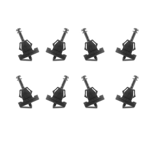
8pcs headlight adjusters with screw bases, replace the stripped out torx head adjusters and allow you to adjust the beam angle of the headlights just as intended.
Accessing Adjusters Through the Engine Bay
Once you’ve gathered your tools and prepared your workspace, locate the adjustment screws by opening your hood and examining the rear of each headlight assembly. Engine bay access provides direct reach to both vertical and horizontal adjusters. You’ll find vertical adjustment screws positioned on top of the housing, accepting a Phillips screwdriver or socket through a tube assembly. Horizontal adjusters typically sit along the side of the housing, often requiring a Torx bit or socket driver.
Turn vertical screws clockwise to raise the beam’s cutoff line for proper headlight alignment. Rotate horizontal screws until the brightest spot aligns with your marked reference line. These adjustment screws differ from mounting hardware—they’re specifically designed for aiming. Always verify you’re turning adjustment mechanisms, not structural fasteners, to prevent damaging your headlight assembly during alignment procedures. Proper beam alignment is especially important when upgrading to LED bulbs, as their increased brightness levels require precise aiming to avoid blinding oncoming drivers. Before making adjustments, check your owner’s manual to identify the specific location of adjustment screws for your vehicle model. Modern headlight upgrades like LED bulb options can enhance visibility, making proper beam alignment even more critical for optimal performance and safety.
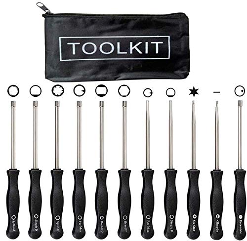
Carburetor Adjustment Tools Fits kinds of brands Including Sears, Craftsman, Poulan, Husqvarna, Weedeater, Echo, Toro, Ryobi, Homelite, and anything else that utilizes the splined adjustment screws. So AKA Husgvarna Carburetor Adjustment Tool,Stihl Carburetor Adjustment Tool,Weedeater Carburetor Adjustment Tool,2cycle Carburetor Adjustment Tool,Walbro Carburetor Adjustment Tool,Poulan Chainsaw Carburetor Adjustment Tool,Carburetor Adjustment Tool Set,Craftsman Screwdrivers Set.

Carburetor Adjustment Tool Kit,fits many brands including: Sears, Craftsman, Poulan, Weedeater, Echo, Toro, Ryobi, Homelite, and anything else that utilizes the splined.Also call Husgvarna Carburetor Adjustment Tool,Carburetor Adjustment Tool,Weedeater Carburetor Adjustment Tool,2cycle Carburetor Adjustment Tool,Walbro Carburetor Adjustment Tool,Poulan Chainsaw Carburetor Adjustment Tool,Carburetor Adjustment Tool Set,Craftsman Screwdrivers Set.
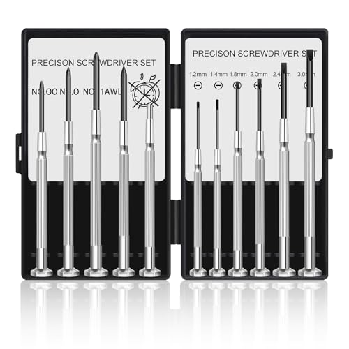
Different Size: Our tiny screwdriver set includes11 different screwdrivers. 3 Phillips head screwdriver sizes (#00, #0, #1) and 6 flat head screwdriver sizes (1.2mm, 1.4mm, 1.8mm, 2.0mm, 2.4mm, 3.0mm), 1 Awl; 1 Magnetic. 11 kids of sizes meet your multi kinds of needs in daily life, such as table battery covers off for toys and replace the batteries
Reaching Adjusters From Wheel Wells and Below
When engine bay access proves difficult or impossible, wheel well access and undercarriage routes provide alternative pathways to your headlight adjustment screws. You’ll need to remove plastic fender liner clips or screws to expose adjusters positioned near the wheel well’s inner edge. Insert your screwdriver through housing notches at angles dictated by fender proximity. Some vehicles feature side guides specifically designed for wheel well reach.
Underbody techniques require a long screwdriver to reach vertical adjusters beneath the headlight assembly. Before accessing from below, bounce your suspension to settle ride height on level ground. You’ll find toothed wheels, hex bolts, or Phillips screws visible below the projector housing. Always wear gloves when working near these components to protect your hands from sharp edges and dirt. Confirm proper tire pressure and verify alignment at twenty-five feet post-adjustment to meet DOT standards. Use painter’s tape to mark reference points on the wall or garage door before making adjustments.

1 unit of front headlight adjustment screw driver tool ONLY for 2018-2022 JL.

Optimal Length and Angled Head: The 16.34-inch (41.5 cm) length and 110° head angle provide excellent reach and maneuverability for hard-to-access carburetor screws on multi-cylinder motorcycles.

Carburetor Adjustment Tool keeps 2 cycle small engines running well. Must have for 2 Cycle small engines to keep them in good condition. Replacement for ZAMA, STIHL, Husqvarna, Poulan, Weedeater, Echo, Homelite, Ryobi, MTD, Troy-Bilt, Toro; string trimmer, chainsaw, leaf blower, hedge trimmer, edger, pole pruner and anything else
Locating Hidden or Internal Adjustment Points
Beyond wheel well and undercarriage routes, many headlight assemblies conceal adjustment screws inside the housing itself, requiring partial or complete unit removal to access them. Hidden screw identification begins with your owner’s manual diagrams, which reveal unmarked adjuster placements specific to your model. BMW F30 vehicles demand screwdriver insertion into concealed housing spots accessible only after disassembly. The 2003 Mercury Marquis positions screws adjacent to internal landmarks, while 1999-2004 Ford Mustangs limit adjustments to vertical-only internal hex tabs.
Internal access techniques involve safely disconnecting electrical connectors, removing retaining bolts, and carefully extracting the headlight assembly from its mounting point. Once the plastic casing opens, you’ll locate adjusters that vary by manufacturer—some use Phillips heads, others require hex drivers. Before beginning internal adjustments, ensure you have replaced your headlight bulb to confirm proper illumination during the alignment testing process. Ford OEM headlights feature a cutout in the installation that allows the adjustment tool to fit through for easier access without full removal. If your headlights appear cloudy or hazy during this process, consider using wet sanding and polishing techniques to restore clarity before finalizing your adjustment work. Adjuster placement often remains unmarked without disassembly, necessitating systematic visual inspection of the reflector assembly’s perimeter and rear mounting points.
Adaptive and Electronic Headlamp Systems
While conventional headlights rely on fixed reflectors and manual adjusters, adaptive and electronic headlamp systems introduce motorized actuators and auto-leveling sensors that dynamically shift beam patterns. These systems complicate adaptive headlight adjustments because auto-leveling integration limits full manual override, often masking alignment issues until component failure occurs.
You’ll find vertical adjustment screws—frequently white—accessible under the hood with a Phillips screwdriver. Electronic beam control systems use gears actuated through small slots: turn clockwise to raise the beam, counterclockwise to lower. Horizontal adjusters may hide behind covers or fender liners, requiring plastic piece removal for access. Push actuators deeper from the bottom or side before turning screws to guarantee proper engagement. Adaptive units risk popping out of position, creating hot spots or dead zones if actuator depth isn’t secured. When the adjuster mechanism snaps back after being raised, inspect for misalignment inside the headlight assembly to ensure components engage properly with the adjustment screw.
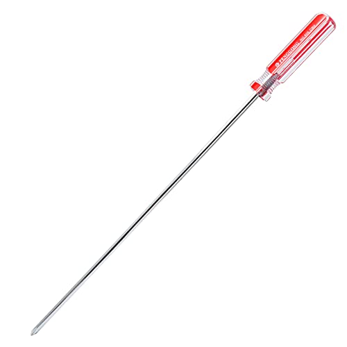
Package Content: 1 x Extra Long Phillips Screwdriver 10 Inch, which is the ideal size and length for the job. The longer length allows you to easily enter the place.

STRENGTH AND DURABILITY: Made of heat-treated alloy steel

STRENGTH AND DURABILITY: Made of heat-treated alloy steel
Troubleshooting Missing, Broken, or Stripped Adjusters
Three common adjuster failures—missing, broken, or stripped screws—demand distinct diagnostic approaches before you attempt realignment. For missing adjusters, consult your owner’s manual to locate hidden positions inside plastic casings or verify aftermarket headlight compatibility. Broken adjusters reveal themselves when clockwise turns fail to pull the headlight inward—apply lubricant before testing counterclockwise movement. Stripped screws won’t respond to standard Phillips screwdrivers; upgrade to 6mm or 8mm Allen key sockets with proper lubricant application at the screw base. Effective adjustment troubleshooting requires marking your vehicle’s center axis with tape, blocking one headlight with cardboard, and confirming the brightest spot sits 2 inches below axis. Repair strategies include purchasing model-specific replacement screws with retaining shields or accessing internal slide levers after removing lamp units.


