To wire headlights to a toggle switch, you’ll need to install a 4-pin automotive relay between the switch and headlights. Connect pin 85 to ground, pin 86 to your 20A-rated toggle switch with a 5A fused control circuit, pin 30 to fused battery power (15-30A), and pin 87 to the headlights. Use 14-16 gauge wire for power circuits and guarantee solid ground connections with ring terminals on bare metal surfaces. This relay-based configuration protects your switch from high-current loads while maintaining circuit efficiency, and there’s additional guidance on testing procedures and troubleshooting techniques to verify proper operation.
Essential Components and Tools Required
Successfully wiring headlights to a toggle switch requires five critical electrical components working in concert: a properly rated toggle switch, an automotive relay, appropriately sized fuses, quality wiring, and secure connectors. You’ll need a 20A-rated automotive toggle switch to trigger a 4-pin or 5-pin relay that handles the high current load, protecting headlight brightness and circuit integrity. Use 14-16 gauge wire for headlight power and 18-20 gauge for control circuits, with inline fuses (5-10A for relay control, 15-30A for headlight power) ensuring wiring safety. Essential tools include wire strippers, crimpers, a multimeter for continuity testing, and heat shrink tubing for moisture-resistant connections. To maintain long-term headlight performance and clarity, consider applying protective clear coats after installation to prevent oxidation and degradation. Unlike daytime running lights which are standard on many modern vehicles, custom headlight wiring systems allow for greater control over when your lights are active. Cable ties, proper grounding hardware, and crimp connectors complete your installation kit, guaranteeing reliable headlight operation. For low and high beam functionality, a 3-position toggle switch allows you to control both beam settings from a single mounting point.

Feature: The SPST toggle switch waterproof is made of metal and bakelite Material. Delicate appearance with strong Construction. Look chic and high-end on your equipment.

Product Features: This waterproof toggle switch made of metal and bakelite, with a waterproof cover, not only has an exquisite appearance and solid structure, but is also effectively weatherproof and improves the quality of the equipment.

Safety Protection: This truck rocker switch control uses copper-plated silver contacts, has good electrical conductivity, and uses high-quality materials and flame-retardant casing for high safety
Understanding the Role of Automotive Relays in Headlight Circuits
Among all the components required for your headlight toggle switch installation, the automotive relay stands as the most technically important element that separates amateur wiring from professional-grade electrical systems. Understanding relay function is essential: your toggle switch carries only 100-200 milliamps of control current while the relay’s contacts handle the full headlight load directly from your battery. This configuration dramatically improves circuit efficiency by eliminating voltage drop that occurs when high-amperage current travels through long wire runs and small switches. You’ll achieve noticeably brighter headlights because the relay delivers constant full voltage regardless of control wire gauge. The relay also protects your toggle switch from overheating and failure by isolating it from high-current demands, ensuring your electrical system operates safely and reliably for years. A healthy relay coil typically shows between 50Ω and 200Ω resistance when tested with a multimeter to verify proper operation. When selecting a replacement bulb, you should consider LED and HID conversion kits as premium alternatives that can further enhance your lighting performance beyond what a standard relay installation provides. Most headlight relays feature four or five terminals numbered 30, 85, 86, 87, and sometimes 87a, with terminals 85 and 86 controlling the electromagnetic coil while terminals 30 and 87 handle the high-current switching function.
Selecting the Right Toggle Switch for Your Headlight System
Three critical specifications determine whether your toggle switch will function reliably in a headlight circuit: current rating, voltage compatibility, and pole configuration. You’ll need a switch rated at minimum 20A @ 12V to handle headlight loads without overheating. When choosing configurations, select SPST for basic ON/OFF control or SPDT for dual-mode operation like high/low beam switching. Evaluating durability requires examining environmental protection features—look for IP67-rated sealed switches with rubber boots if mounting under-hood or in weather-exposed locations. Heavy-duty construction resists vibration and impact inherent in automotive environments. Consider illuminated switches with LED indicators for visual feedback of circuit status. Verify the switch fits standard 1/2″ mounting holes and provides .250″ tab terminals for secure wire connections that won’t loosen from vehicle vibration. For installations requiring enhanced safety, aircraft style covers prevent accidental activation and fit standard 1/2 inch diameter stems.
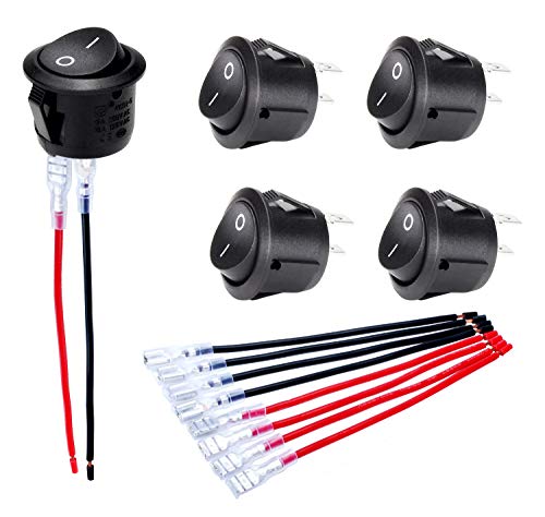
Features: "O I" marked on black button 12V Rocker Switch with 5 sets of wires(#187 Lock Terminals on end) for switch easy connection.

Feature: The Safety cover toggle switch is 2 Pin SPST(single pole single throw), designed with rocker style, easy to turn ON OFF. The switch rating is 20A 12V DC; 15A 250VAC; 20A 125VAC Heavy Duty.

Function: SPST 2 PIN ON/OFF marine rocker switch 12V. 2 Pin rocker switches make the wiring become simple, easy and convenient for you.
Circuit Layout and Relay Pin Configuration
With your toggle switch selected, you’ll need to configure the electrical circuit that connects it to your headlights through a relay system. Standard 4-pin automotive relay types follow a consistent configuration: pin 85 connects to ground, pin 86 receives control voltage from your toggle switch, pin 30 links to fused battery power, and pin 87 outputs to the headlights when energized.
Your toggle switch requires a 5A fuse protecting the control circuit, matching appropriate switch ratings for low-current operation. The relay output circuit demands a separate 10A fuse between pin 30 and the power source. When you activate the toggle switch, voltage flows to pin 86, energizing the coil and closing the contact between pins 30 and 87, delivering full battery power to your headlights while protecting your switch from high-current loads. Most vehicles use either one or two bulbs per headlight assembly depending on the design, so verify your specific configuration before finalizing connections. Before installation, ensure you have access to the headlight assembly for proper connection to the relay output. Always verify energy disconnection using a non-contact voltage detector before beginning any wiring work to ensure a safe installation environment.

Upgraded Version - Automotive relays built in fuse socket included 30A blade fuse with heavy duty 14AWG wires for main contact. no need of a separate fuse holder, saving space and money. 4-Pin SPST (Single Pole Single Throw) Relay.
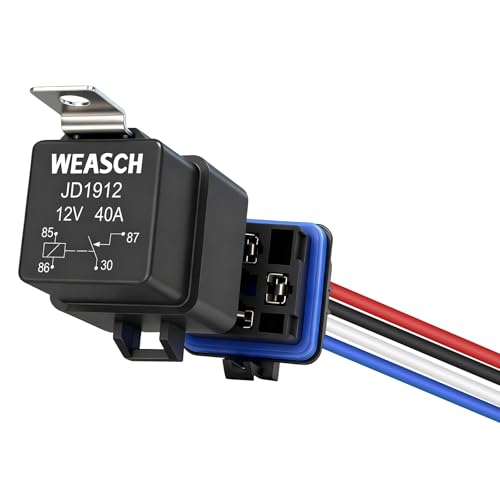
Rated Coil Voltage: 12V DC; Max. Rated Switching Current: 40A; Coil Power: 1.8W; Coil Resistance: 80 Ω

Never go beyond its capabilities. Try to stay 10 to 15% below the rate for
Step-by-Step Wiring Process
Before connecting any wires, gather your tools and materials on a clean workspace where you can organize components systematically. Start by selecting appropriate toggle switch types—2-prong or 3-prong—rated for automotive 12V systems. Wire gauge selection is critical; use 16-18 AWG for headlight circuits to handle current safely.
Connect the fused 12V power wire to the toggle switch’s input terminal. Attach the output terminal to your relay coil or headlight positive wire. If using an illuminated switch, connect the ground terminal to chassis ground. The white wire from the switch connects to pin 86 on the relay, with pin 30 linked to a 10 amp fuse for headlight operation. For additional protection and waterproofing, cover all connections with heat shrink tubing after securing them with crimps or solder. Applying UV sealant around wire connections can also provide extra protection against moisture and corrosion over time.
Before final installation, verify voltage at each terminal using a multimeter. Test headlight operation, confirming they illuminate only when the switch is engaged, with no flickering or voltage leakage.
Proper Fuse Selection and Inline Installation
Selecting the correct fuse protects your headlight circuit from overcurrent conditions that can damage wiring, melt insulation, or cause electrical fires. Choose a fuse rating between 125% to 135% of your headlights’ maximum operating current—typically 15-20A for standard automotive headlamps. Ascertain the rating doesn’t exceed your conductor’s ampacity. Use a time-delay fuse to handle initial inrush current when headlights activate without nuisance blowing.
Install the fuse inline between the battery positive terminal and toggle switch using a weatherproof holder with adequate environmental resistance against moisture, vibration, and temperature extremes. Verify the fuse’s voltage rating exceeds your system voltage by at least 20%, and confirm its interrupting capacity surpasses potential fault currents. Ensure the breaking capacity exceeds the maximum fault current your automotive electrical system can produce under short-circuit conditions. Secure all connections mechanically and electrically, ensuring accessibility for future inspection and replacement.

Medium duty time-delay plug fuse

Used in residential or light-duty motor circuits

Establishing Secure Ground Connections
A secure ground connection forms the foundation of reliable headlight operation, completing the electrical circuit by providing a low-resistance return path from the bulbs back to the battery’s negative terminal. Select bare, unpainted metal surfaces on the chassis or firewall, grinding away rust, paint, or corrosion to expose clean metal. Use 8-10 AWG wire with properly crimped ring terminals and corrosion-resistant hardware. Apply grounding techniques such as star washers to maintain tight contact under vibration, and keep ground wires short to minimize resistance. For corrosion prevention, coat connections with dielectric grease and seal them with heat-shrink tubing. Position grounding points as close as possible to the headlights, ensuring solid metal-to-metal contact that won’t degrade over time. The ground connection should maintain resistance under 1-ohm to ensure proper fault current handling and prevent voltage buildup on accessible metal surfaces.
Wiring Illuminated and LED Toggle Switches
Understanding the electrical architecture of illuminated toggle switches prevents wiring mistakes that can damage sensitive LED components or create unsafe circuits. These switches contain internal LEDs requiring separate illumination circuitry with dedicated terminals for power and ground. You must observe switch polarity when connecting LED terminals—reversing positive and negative leads prevents illumination. Wire the switch’s input terminal to a fused 12V supply, the output terminal to your relay coil, and the LED ground to chassis ground. The relay isolates high-current headlight loads from delicate switch contacts. Most illuminated switches feature three terminals: power input, load output, and LED ground. Some rocker switches include four terminals with an additional terminal dedicated to independent top light operation, providing enhanced visibility options. Always consult manufacturer wiring diagrams to identify correct terminal functions, and refer to proper beam alignment guidelines to ensure your headlights function safely once wired. Install an appropriately-rated inline fuse on the positive supply line to protect both switching and illumination circuits from overload conditions.

Function: Blue LED toggle switch with 3 pin blade type terminals, SPST design(single pole single throw), Rated at 30A 12V DC and 15A 24V DC. Mounting hole size is 0.47 inches (12mm).

Function: 12V LED lighted toggle switch with 3 pins, SPST design(single pole single throw), designed with rocker style easy to turn ON/OFF.

Features: This truck rocker switch control uses copper-plated silver contacts, has good electrical conductivity, and uses high-quality materials and flame-retardant casing for high safety. Equipped with output short circuit, overload & polarity reverse protection. Up to 10000 times of ON/OFF operating life span.
Testing Your Headlight Circuit Before Final Installation
Before energizing your newly wired headlight circuit, you must conduct systematic electrical tests to verify component integrity and prevent potential failures that could leave you stranded or create fire hazards. Start with visual inspection—examine all wiring, connectors, and terminals for corrosion or damage, comparing against your circuit diagrams. Set your multimeter to DC voltage mode and verify 12V at headlight terminals when the toggle switch activates. Test continuity through each wire segment in resistance mode, confirming no breaks exist. Perform voltage drop testing under load conditions; excessive drops indicate poor connections requiring immediate correction. Connect the black lead of the multimeter to a good ground such as the vehicle frame or negative battery terminal to ensure accurate voltage readings. Check grounding points are clean and secure. These safety precautions guarantee reliable operation. Only after confirming proper voltage distribution, zero shorts, and minimal resistance should you proceed with permanent installation.
Troubleshooting Common Wiring Issues and Maintenance Tips
Even when you’ve meticulously wired your headlight toggle switch circuit, electrical faults can emerge over time through vibration, heat cycling, and environmental exposure. Common wiring complications include loose connectors causing flickering—detectable by gently tapping the assembly during operation—and corroded terminals blocking current flow. Clean corroded connections with electrical contact cleaner and verify ground integrity by testing continuity to the battery’s negative terminal. Use a multimeter to confirm power at headlight connectors when the toggle switch activates. Check the headlight fuse for broken filaments and swap relays with known good units to isolate failures. Connection maintenance requires inspecting harnesses for frayed wires, tightening terminals, and ensuring proper routing away from sharp edges and heat sources to prevent premature degradation. Poor grounding can cause dim lights, so inspect and clean ground connections near the headlight assembly to ensure optimal performance.